
Factory Simulation
 As you know, with the increasing development of technology and science all of factories for covering of precision control for industrial equipment using PLC system(Programmable Logic Controller) instead of old electromechanical relays. In fact PLC is a small computer used for automation of real world process such as control of machinery on factory assembly lines.where older automated systems would use hundreds or thousands of relays,a single PLC can be programmed as a replacement. PLC is a combination of solid state devices 2 perform specific task using CFS(control system flochart) and Ladder programming plcs are used to control certain process like power plant its more reliable than pc,cost efficient and small size.
We can using PLC technology for :
As you know, with the increasing development of technology and science all of factories for covering of precision control for industrial equipment using PLC system(Programmable Logic Controller) instead of old electromechanical relays. In fact PLC is a small computer used for automation of real world process such as control of machinery on factory assembly lines.where older automated systems would use hundreds or thousands of relays,a single PLC can be programmed as a replacement. PLC is a combination of solid state devices 2 perform specific task using CFS(control system flochart) and Ladder programming plcs are used to control certain process like power plant its more reliable than pc,cost efficient and small size.
We can using PLC technology for :
- Manufacturing Industry
- Travel Industry
- Aerospace
- Printing Industry
- Food Industry
- Textile Industry
- Hospitals
- Film Industry
- Corrugating
- Plastics Industry
- Agriculture
- Foundry
In this project i had to make a Maquettes like industrial equipment for using PLC LOGO! and shows functions of PLC system VS problems in industrial equipments. Here is a list of all electrical parts:
|
Modeling Devices |
Electrical parameters |
|
LOGO
RC230 – 0BA5
Micro Controller: PIC16F628 PIC16F873 PIC16F876 Transistors: C9013 – NPN C3904 – NPN C3006 – PNP Regulator: LM7805 LM7809 LCD: 2*16 Characterize LCD Sensors: Temperature: DS1820 Counter: EX – 07N – NPN Output |
POWER SUPPLY: 220VAC , 12VDC , 5VDC POWER CONSOMPTION: Conveyour system: 450ma Label Checking system: 110ma Heating System: Heater: 210ma Fan: 450ma Total: < 4Amp WIRING: 76Meters 24AWG and 27AWG FUSES: 220VAC : 220V – 10A Miniature Fuse 12VDC – 5VDC : 5A Axis Fuse |
The project includes six sections:
Control room

Control of all electrical equipment in this factory with 4 keys,alarm system and monitor. in this keys panel you can see “C” key means Conveyor system and “L” means Label checker system and “H” means Heating system and “12” means 12voltage for some equipment. Alarm system make sound when label checker have problem and call operators in control room until verifying packets.
.
Power Supply
 This box make some voltages for electrical devices in factory, in this factory we need 3 voltage for all purposes, 220v ,12v and 5v.
220V-AC : for PLC system
12V-DC : for cooling , heating ,motor and infra-red sensor(packet counting in conveyor)
5V-DC : for LEDs and microcontroller systems
in this part use 2 types of fuses: miniature 10A and axis 5A.
.
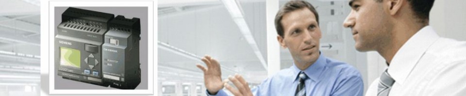
PLC LOGO!
![]() Programmable Logic Controller is heart of computerize system for make reality , security , precision control , fast switching and reaction to the problem that can damage industrial equipment in factory. this plc made by siemens company. all of electrical devices connected to plc logo for automatic controlling with 8 input and 4 output. 0BA5 is code of this plc with 2000byte e2prom for programming with 130 digital gates.
Programmable Logic Controller is heart of computerize system for make reality , security , precision control , fast switching and reaction to the problem that can damage industrial equipment in factory. this plc made by siemens company. all of electrical devices connected to plc logo for automatic controlling with 8 input and 4 output. 0BA5 is code of this plc with 2000byte e2prom for programming with 130 digital gates.
.
Conveyor System
 The duty of conveyor system is control movement of packets product in factory and counting all of them to 30 packets and then wait for 10 seconds until lift truck doing its duty. in this system you can see numbers of packet on the 2 red digits front of conveyor and green light in the right corner shows you that system is working true and red light indicate system goes stop. this conveyor made with stepper motor that control with PIC microcontroller and 1.8 degrees in per step. when packets counting up to 30 , conveyor sending message to PLC LOGO and shows that counting duty done , in this this plc system will stop conveyor system for 10 seconds and after that repeat process again.
.
Label Checker

As you know in the real factory there is unit for checking health of production in the assembly line called QC(Quality Control) unit. in this project you can see a optical robot for checking labels packet and analyzing virtually. if packet haven’t any problem can across from under optical robot.in this part you can see green packet means healthy packet and red packet means packets have no label. if any packet haven’t label optical robot scan that and send alarm signal to PLC system and after analyzing plc start alarm in the control room.
.
Heating System
 When starting heating system , temperature goes high continuously. in the heating system used DS1820 digital temperature sensor for making precision temperature signal and you can see temperature on the LCD on the top. in this part define temperature range between 60-70 degrees of centigrade. heating system should make balance between this range , when temperature goes high upper of 70 degrees , system send message to PLC system and after analyzing plc start cooling system until temperature goes down.
.
See some views of Factory simulation:


![]()
